
How to Choose the Right Valve Actuator?
Choosing the right Valve Actuator is not a catalog exercise. It is a decision about movement, safety, control, and maintenance. A valve may sit quietly for months, then face full pressure during one critical cycle. That moment exposes weak assumptions. In practical plant work, actuator selection begins with the valve, not the motor. Engineers examine torque, travel, operating frequency, fluid temperature, pressure, and available energy. They also confirm whether the valve needs quarter-turn or linear motion. Small details matter. A mismatched actuator can cause slow response, unnecessary wear, or incomplete shutoff.
Pneumatic, electric, and hydraulic options each solve different problems. Pneumatic units often provide fast action and useful fail-safe behavior, but they need clean, reliable air. Electric actuators support accurate positioning and easier local integration, although heat, moisture, and power loss require careful planning. Hydraulic systems deliver high force, yet their pumps, hoses, and maintenance demands deserve honest evaluation. A qualified engineer should compare required torque with the valve’s breakaway torque, not only its running torque. Safety factors should reflect real conditions, including cold starts, corrosion, packing friction, and infrequent operation. Datasheets help, but field experience can reveal what a brochure misses.
The best choice also considers the complete lifecycle. Look at enclosure protection, manual override, feedback signals, calibration, spare parts, and technician access. A low purchase price may become expensive when inspection takes two hours or replacement parts arrive slowly. Verify ratings, control compatibility, and applicable industrial standards with the manufacturer or a competent specialist. No selection is perfect. Conditions change, and calculations can be based on incomplete data. That is why responsible teams document assumptions, test critical assemblies, and review performance after installation. The right Valve Actuator should move the valve reliably, protect the process, and remain understandable to the people who maintain it.
Valve Actuators: Definition, Purpose, and Main Types
How to Choose the Right Valve Actuator?
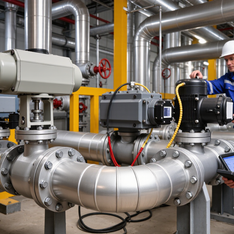
A valve actuator is a device that opens, closes, or positions a valve. It converts energy into controlled mechanical movement. In a processing line, the actuator may turn a quarter-turn valve or move a linear valve stem. Its purpose is practical: regulate flow, isolate equipment, and support safe, repeatable operation. The right choice depends on torque, travel, speed, control accuracy, and operating conditions.
Electric actuators suit locations with reliable power and precise positioning needs. Pneumatic actuators provide fast movement and simple control, especially where compressed air is already available. Hydraulic actuators deliver high force for demanding valves, but they require careful fluid management. Manual actuators remain useful for small systems, emergency isolation, or infrequent adjustment. They are not always the cheapest option after labor is considered.
Look beyond the actuator alone. Check valve torque throughout its full travel, not only at startup. Confirm temperature, humidity, dust, corrosion, and available space. A fail-open or fail-closed function may protect equipment during power loss. Control signals and feedback devices must also match the control system. I have seen installations fail because engineers selected nominal valve size instead of actual operating torque. That mistake is easy to repeat. Leave a reasonable safety margin, but avoid excessive sizing, which can increase cost and reduce control sensitivity. Test the complete valve-actuator assembly before service.
How to Choose the Right Valve Actuator? - Valve Actuators: Definition, Purpose, and Main Types
| Actuator Type | Definition and Operating Principle | Typical Valve Compatibility | Energy Source | Common Control Mode | Typical Fail Action | Key Advantages | Important Limitations | Best-Fit Applications |
|---|---|---|---|---|---|---|---|---|
| Electric Rotary | An electric motor drives a gearbox to rotate the valve stem or shaft to a specified position. | Ball, butterfly, plug, and other quarter-turn valves; multi-turn versions can operate gate and globe valves. | Electric power, commonly low-voltage DC or single- or three-phase AC. | On/off, modulating, position control, or network-based control. | Usually stays in position during power loss unless equipped with a spring-return or battery-backed system. | Precise positioning, easy integration with digital control systems, and no instrument-air supply required. | Slower than many pneumatic systems; motor and electronics require suitable environmental protection. | Water treatment, HVAC, utilities, process plants, and applications where electrical control is readily available. |
| Pneumatic Rotary | Compressed air moves a diaphragm or piston to produce rotary torque, generally through a rack-and-pinion or scotch-yoke mechanism. | Primarily ball, butterfly, and plug valves. | Compressed air, commonly supplied through a filter-regulator and control valve. | Fast on/off operation or modulating control with a positioner. | Spring-return designs can fail open or fail closed, depending on actuator and valve arrangement; double-acting designs commonly fail in place. | Fast response, high power-to-weight ratio, and suitability for hazardous areas when correctly configured. | Requires reliable, clean, dry compressed air; air leakage can increase operating cost. | Chemical processing, oil and gas, industrial automation, and emergency shutoff service. |
| Pneumatic Linear | Compressed air moves a diaphragm or piston in a straight line to extend or retract an actuator stem. | Globe, diaphragm, pinch, and other linear-motion valves. | Compressed air. | Modulating control through a positioner or simple open/close control. | Spring-return units can be configured to fail open or fail closed; double-acting units generally require a separate fail-safe arrangement. | Suitable for accurate throttling and provides a straightforward stem force arrangement. | Needs compressed air and may require adequate installation space above the valve. | Steam, water, gas, and process-fluid flow control using globe or diaphragm valves. |
| Hydraulic | Pressurized hydraulic fluid acts on a piston or vane to generate linear force or rotary torque. | Large ball, butterfly, plug, gate, and globe valves, depending on actuator configuration. | Hydraulic fluid supplied by a power unit or hydraulic control system. | On/off or modulating control; remote hydraulic control is also possible. | Can be engineered for fail open, fail closed, or fail in place using springs, accumulators, or other stored-energy systems. | Very high force and torque density; effective for large valves and high-pressure service. | More complex installation, potential fluid leakage, and higher maintenance requirements than many electric solutions. | Large pipelines, hydroelectric facilities, offshore systems, and demanding heavy-duty applications. |
| Electro-Hydraulic | An electric motor drives a hydraulic pump and control system, combining electrical command with hydraulic actuation force. | Large quarter-turn or linear valves requiring high output force and integrated fail-safe capability. | Electric power with stored hydraulic energy where required. | Remote, automatic, on/off, or modulating control. | Can provide fail open, fail closed, or fail in place through an accumulator and control logic. | Combines high thrust or torque with precise electronic monitoring and control. | Higher purchase cost and system complexity; hydraulic maintenance is still required. | Critical pipeline isolation, power generation, marine systems, and remote installations. |
| Manual Gear or Handwheel | An operator turns a handwheel, lever, or gearbox to move the valve without an external power source. | Gate, globe, ball, butterfly, plug, and other manually operated valves. | Human effort. | Local open/close or manual throttling where permitted by the valve design. | No automatic fail action; the valve remains at its last manually established position. | Simple, low-cost, independent of utilities, and easy to inspect. | Not suitable for frequent remote operation, rapid emergency response, or inaccessible valve locations. | Small facilities, maintenance isolation, low-cycle service, and locations without power or air. |
Selection Criteria
| Decision Factor | What to Check | Why It Matters |
|---|---|---|
| Valve motion | Determine whether the valve requires quarter-turn, multi-turn, or linear movement. | The actuator output must match the valve stem movement and mounting interface. |
| Required torque or thrust | Use the valve manufacturer’s operating torque or stem-thrust data, including breakaway and seating requirements. | An undersized actuator may fail to move or properly shut off the valve; excessive output can damage the valve stem or seat. |
| Operating speed | Define the required opening or closing time and acceptable ramp rate. | Fast closure can improve isolation but may create pressure surges or water hammer in liquid systems. |
| Duty cycle | Estimate cycles per hour, daily operating time, and whether continuous modulation is required. | Motor heating, seal wear, and actuator life depend strongly on operating frequency and duration. |
| Fail-safe requirement | Select fail open, fail closed, or fail in place based on the process safety assessment. | The correct failure position helps protect personnel, equipment, and the process during loss of power or control signal. |
| Environment | Review temperature, moisture, dust, corrosion, vibration, submergence, and hazardous-area classification. | The enclosure, materials, electrical protection, and actuator technology must suit the installation conditions. |
| Available utilities | Confirm the availability, reliability, and quality of electric power, compressed air, or hydraulic power. | The actuator should remain reliable without requiring an impractical or costly support system. |
| Control and feedback | Specify local control, remote control, position feedback, diagnostics, communication, and signal type. | Matching the actuator to the control architecture improves monitoring, commissioning, and maintenance. |
| Installation and maintenance | Check available space, mounting orientation, accessibility, spare parts, and service requirements. | A technically suitable actuator may still be impractical if it cannot be safely installed or maintained. |